Cheers buddy.
Just concerned the machinist supplied 2 rings needing pin and hook spanners to fit if only one needs to be used.
The hook type is too shallow to allow the stem bolt to bite.
Dust cap is included.
Chaars!
Hello Guest User,
Please feel free to have a look around the forum but be aware that as an unregistered guest you can't see all of it and you can't post.
To access these 'Registered Users Only' areas simply register and login.
Please feel free to have a look around the forum but be aware that as an unregistered guest you can't see all of it and you can't post.
To access these 'Registered Users Only' areas simply register and login.
Z800 Cafe Chopper Fighter thing...
Moderators: chrisu, paul doran, Taffus, KeithZ1R

-
Royalratch
- 100Club

- Posts: 345
- Joined: 3rd Jul 2009
- Location: London
-
Royalratch
- 100Club
- Posts: 345
- Joined: 3rd Jul 2009
- Location: London
Hello all.
Yes, the world's longest Z build is alive and well, just been in hibernation due to all kinds of boring nonsense.
BUT! I have to get it on the road this spring as the garage where the build is kept is being demolished. So even if I don't complete it myself I'll hand it over to my engine builder to complete - he also does lots of custom work / fabrications so hopefully it will be on the road by April!
A quick question to get the ball rolling again.
I'm just putting the finishing touches to the loom which is made from scratch. I'm wiring in the Reg/Rec and have a few questions about cable colours and how it plugs in.
I'm using an aftermarket Reg/Rec for a Z650 with 3 Yellow wires, 1 Brown, 1 Black and 1 White. Can anyone confirm that the below is correct:
3 Yellows TO Stator / Generator
1 Brown TO Battery+ terminal - This is the charging wire and should be fused?
1 Black TO GROUND - Direct to Battery- Terminal or any good ground point?
1 White TO ? This is the control wire I think to regulate charging current - where should enter the circuit? I'm using keyless ignition managed by a MotoGadget unit so the ignition circuit is not straightforward.
Help appreciated! Pics on the way.

-
Royalratch
- 100Club
- Posts: 345
- Joined: 3rd Jul 2009
- Location: London
-
Ginger Bear

- Hardcore

- Posts: 5512
- Joined: 16th Dec 2008
- Location: In the Dark.
- Contact:

-
Royalratch
- 100Club
- Posts: 345
- Joined: 3rd Jul 2009
- Location: London
-
Royalratch
- 100Club
- Posts: 345
- Joined: 3rd Jul 2009
- Location: London
Another quick Q.
Want to power this thing up and check all circuits but the M-Unit requires a switched 12V to the LOCK terminal to actually switch it on - even though its connected to the battery.
However, I don't have an ignition switch and the keyless remote is not at the garage.
How can I 'improvise' a switched 12V+?
Direct + from battery do the trick? Or am I sending all the cranking amps down too thin a wire...?

-
Royalratch
- 100Club
- Posts: 345
- Joined: 3rd Jul 2009
- Location: London
Thanks lads - got it working. This sucker will be ready to fire up soon as it will be off to Debbens for a carb set-up and some minor bits and bobs and then MOT time! Here's a short viid:
https://www.youtube.com/watch?v=XXQFkbJ ... e=youtu.be
Using an off the shelf $40 dual-Switch Bluetooth relay, I was able to create a remote ignition and starter app for my iPhone. Instead of having an ignition barrel and starter button, I can now switch the bike on and start it via my phone from 20ft away. It also keeps the bike's controls area super clean.
This particular relay also includes a temperature sensor that will be fitted to the top of the air-cooled engine next to the spark plugs. This will allow me to take very accurate engine temp readings and even log them at intervals over a ride to monitor engine temps. I can also have my phone alert me via SMS if the engine is overheating. Using a 4G data-enabled relay, I can switch the bike on (and off!) from anywhere in the world.
-
Royalratch
- 100Club
- Posts: 345
- Joined: 3rd Jul 2009
- Location: London
Hi all.
Some minor speed bumps on final assembly, if you could wade in with your wisdom - much appreciated!
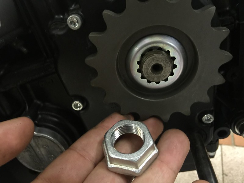
1) Engine Sprocket
Is this the securing washer that should be bent around the nut? Doesn't look like it...?
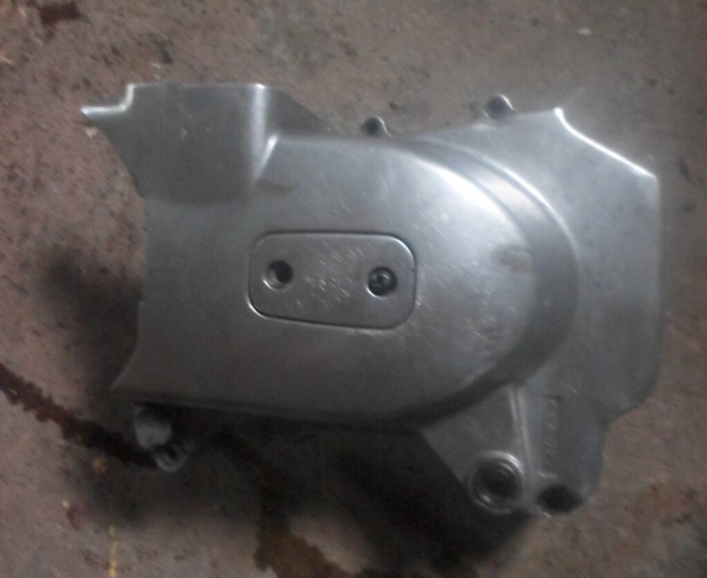
2) Engine Sprocket Casing
This one is from a Z750A and does fit the engine - BUT it could the frame so no way to fit with the engine in place. Is it the wrong one? What case will fit without removing the engine - as I can;t believe you have to do that to remove / refit these???
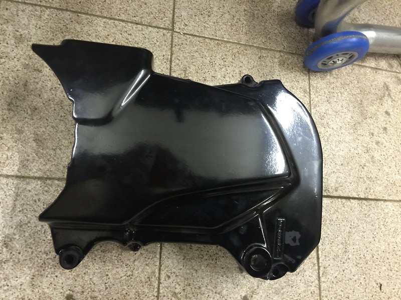
This one appears to have a kick in that corner to clear the frame. Form a 1982 750-H
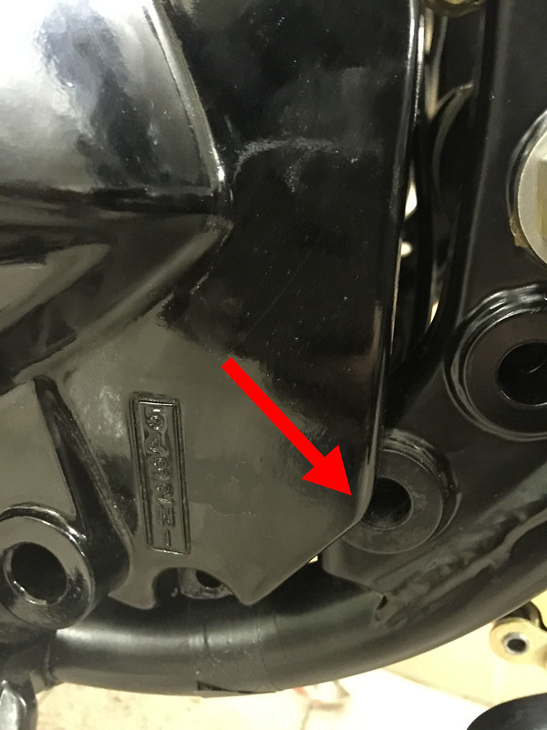
3) Chain fouls the top of the swingarm.
Not a total shock but how much is too much? I calculated the biggest front and rear sprockets I could fit to give me as much clearance as possible. Does the standard Nylon strip really do the job? Or this a result of bad design...?
Some minor speed bumps on final assembly, if you could wade in with your wisdom - much appreciated!
1) Engine Sprocket
Is this the securing washer that should be bent around the nut? Doesn't look like it...?
2) Engine Sprocket Casing
This one is from a Z750A and does fit the engine - BUT it could the frame so no way to fit with the engine in place. Is it the wrong one? What case will fit without removing the engine - as I can;t believe you have to do that to remove / refit these???
This one appears to have a kick in that corner to clear the frame. Form a 1982 750-H
3) Chain fouls the top of the swingarm.
Not a total shock but how much is too much? I calculated the biggest front and rear sprockets I could fit to give me as much clearance as possible. Does the standard Nylon strip really do the job? Or this a result of bad design...?
Who is online
Users browsing this forum: No registered users and 55 guests