Hello Guest User,

Please feel free to have a look around the forum but be aware that as an unregistered guest you can't see all of it and you can't post.

To access these 'Registered Users Only' areas simply register and login.

Z1000J Build

Work in Progress

Moderators: chrisu, paul doran, Taffus, KeithZ1R

Message
Author
Coose
Custard Cream
Custard Cream
Posts: 703
Joined: 20th Apr 2015
Location: North Yorks

#31 PostAuthor: Coose » Mon Jul 04, 2016 6:48 am

LeeJackson wrote:So measuring up I need to shim out 3.5mm and remove same from the outside, unfortunately this particular speedo drive doesn't have much meat on the outside of it to remove, max 2mm.


I picked up a drive from a GPz305 for a fiver and could shave loads off it. It might be worth a trawl through eSkip to see if there's anything you can butcher?

LeeJackson
100Club
100Club
Posts: 458
Joined: 17th Oct 2015
Location: Aberdeen, Scotland

#32 PostAuthor: LeeJackson » Mon Jul 04, 2016 12:14 pm

neilbarrett wrote:I'm going to use the standard speedo on me z1 project with after market wheels but am going a diffent route for the drive ,theres a few different versions of these outrigger plates about ive not chosen one yet my self ,even considered making one ,but will see ,if ihttp://www.jauce.com/auction/h188819149ts of any interest


Now that's a pretty nice solution! Would allow me to keep the clocks while loosing front speedo drive.

Coose
Custard Cream
Custard Cream
Posts: 703
Joined: 20th Apr 2015
Location: North Yorks

#33 PostAuthor: Coose » Wed Jul 06, 2016 8:26 am

zorded wrote:I dont know if this will help at all but its something i have been using for the last 18 months. Things are a bit different now for various reasons.
The key thing which is missing is the dimension from crank centre to ground level. Dont know where it went. Cant find it anywhere.
In this state it handled as well as it had ever done but being me i wanted more and in persuit of ground clearance, i set about it.
TLC is right, its all about the front end geometry and weight distribution to name but two.
Best brakes in the world, nicest wheels, Maxton forks... what ever you like but if it does not work its a nightmare.
To exercise that point and the law of un-intended consequences; i bought and fitted Astralite wheels which as the name implies; weight next to nothing. Great but the original centre of mass was where KHI intended it to be, afterwards it was significantly higher giving a top heavy feel and no longer any flywheel effect from those old boat anchors i had been using.
The advantages for me outweighed the losses but its worthy of some thought.
Tony Foal's book makes very interesting reading but if youre like me it was someone telling you Father Christmas is not a real person!!!!!


Image


AL


Sorry to butt in on Lee's thread, but that is an interesting pic for a geek like me. I've just taken a couple of measurements from my J, and with 360mm rear shocks, a Z1300 18" front wheel (GPz11 rear) and fork springs of unknown origin my head angle is 29 degrees (measured using an inclinometer app on my phone), which in comparison to yours is 61 degrees. I haven’t measured the trail, but assuming your using stock yokes I could probably calculate it from your offset.

With the Davida swinging arm I have a wheelbase of around 1520mm. Sag is set correctly, and other than needing a touch more rear rebound damping and control than my Marzocchi Stradas can give it turns in great, though this will be helped by the 110/130 tyres and geet wide Renthals!

User avatar
Al
Hardcore
Hardcore
Posts: 2811
Joined: 21st Oct 2007
Location: Farnbronx, Sin City, N.E. Hants

#34 PostAuthor: Al » Wed Jul 06, 2016 5:45 pm

This is the situation as of today.
Rake measured directly from PC screen using lines in photo and clear protractor, couldnt find a more accurate way.

Standard J1 rake is 27.5 deg and wheelbase 1520. Mine could be 20mm or more less, but changing sprocket sizes means i need flexibility with the rear eccentrics!!

Standard J2 / B1 / B2 rake is 29 degrees
Standard R1 29 degrees
Standard J3 / R2 27.5 Degrees
*UK Figures*

Crank cantre to floor (measured at the bolt behind cover is 408mm and i think originally it was something like 415 or 420 but i've lost that now.

Image
1981 J1

LeeJackson
100Club
100Club
Posts: 458
Joined: 17th Oct 2015
Location: Aberdeen, Scotland

#35 PostAuthor: LeeJackson » Sat Jul 16, 2016 4:32 pm

So not much progress as I've been working away but I managed to shave enough meat of the casting of the speedo drive to clear the disc surface.. Now if I countersink the disc bolts I'll be laughing. Just need to find a machine shop that speak English. Biggest challenge! Lol So thanks for the suggestions guys.

Still waiting on my yokes and not much else going to happen till I get them. Mr Debben is finalizing my engine though so after holidays I hope I'll get a big push on with this project..

LeeJackson
100Club
100Club
Posts: 458
Joined: 17th Oct 2015
Location: Aberdeen, Scotland

#36 PostAuthor: LeeJackson » Mon Aug 08, 2016 1:57 pm

So more delays.. I waited another few weeks to see if my yokes would eventually turn up, but It doesn't look like it.. So will just have to continue with the standard zephyr ones..

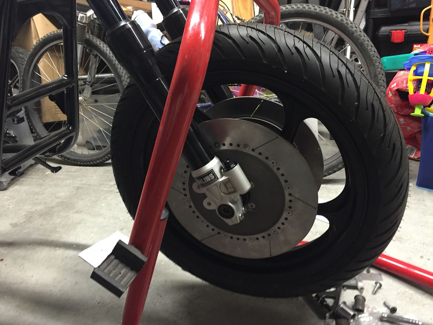
Anyway after Holidays etc time to finally get these discs fitted. I have two options that I can see to make them clear my speedo drive.. Both involve countersinking the bolts, but want to see your opinions.. so made this very rough sketch..

Image

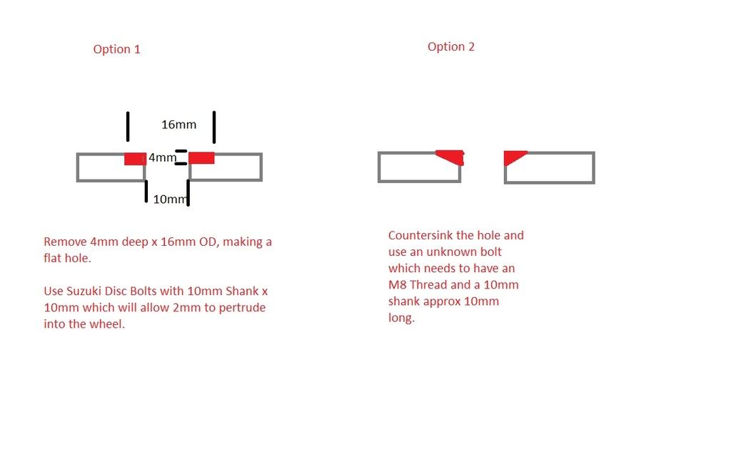
So the first way would be to machine a new flat on the side, 16mm wide by 4mm deep and use the Suzuki Bolts I have here. These discs are pretty think at 12mm, so if I countersink the flat by 4 mm, it leaves 8mm of thickness and the shank of the Suzuki Bolts is 10mm meaning they will enter the wheel by 2mm, which I think is enough to keep everything true? The Complication is getting the flat machined on them because not something I can do myself and since its August in France everyone has shut for the month...

Option 2 would by just to countersink and use a countersunk style disc bolt.. This I can do myself I guess but I have no idea where to buy countersunk M8 molts with a 10mm shank..

Opinions appreciated :)

User avatar
Gus
Hardcore
Hardcore
Posts: 1484
Joined: 17th Mar 2007
Location: Gloucestershire

#37 PostAuthor: Gus » Mon Aug 08, 2016 3:02 pm

Is the M8 thread standard or fine?

Google

m10 countersunk shoulder bolt

Gus
"Set the GRINDER on it"

LeeJackson
100Club
100Club
Posts: 458
Joined: 17th Oct 2015
Location: Aberdeen, Scotland

#38 PostAuthor: LeeJackson » Mon Aug 08, 2016 3:32 pm

Gus the M8 thread is standard. For discs what grade do I need?

User avatar
Gus
Hardcore
Hardcore
Posts: 1484
Joined: 17th Mar 2007
Location: Gloucestershire

#39 PostAuthor: Gus » Mon Aug 08, 2016 3:51 pm

I'm no metallurgist but people make replacement disc bolts from stainless (as seen on ebay) and I have used them.

an M10 countersunk shouldered bolt could be turned down to the required length with a diameter of 8mm and an 8mm thread cut on to it.

That's if you can't find something to work off the shelf.
"Set the GRINDER on it"

LeeJackson
100Club
100Club
Posts: 458
Joined: 17th Oct 2015
Location: Aberdeen, Scotland

#40 PostAuthor: LeeJackson » Sun Sep 04, 2016 12:10 pm

Well some small progress today, finally got round to buying some counterbores and got my discs sorted. Along with slightly modified speedo drive all is well..

Image

Image

Took some measurements and seem to be 1mm out of line, but not sure you can get that accurate a measurement off castings etc.. I'm thinking it's probably ok ? Maybe will try and get hold of a shim to just set my mind at ease.. :)

Now to make the caliper brackets and next week the engine should be back from Debben's so will make some progress on the setup of suspension etc..

User avatar
harri183
Custard Cream
Custard Cream
Posts: 785
Joined: 20th Feb 2013
Location: N Yorkshire

#41 PostAuthor: harri183 » Sun Sep 04, 2016 2:25 pm

Looking real good would love to be able to turn and make my own stuff. More pics and updates please :)

LeeJackson
100Club
100Club
Posts: 458
Joined: 17th Oct 2015
Location: Aberdeen, Scotland

#42 PostAuthor: LeeJackson » Sun Sep 04, 2016 6:36 pm

harri183 wrote:Looking real good would love to be able to turn and make my own stuff. More pics and updates please :)


Not much machining done on my behalf unfortunately, not enough space here. Dave from Sasei helping me out with the brackets to marry the AP calipers up to the forks, just need to make my wooden dummy plates first to double check the sizes..

User avatar
tlc
Hardcore
Hardcore
Posts: 4135
Joined: 6th Nov 2007
Location: Aylesbury

#43 PostAuthor: tlc » Mon Sep 05, 2016 7:38 am

LeeJackson wrote:Took some measurements and seem to be 1mm out of line, but not sure you can get that accurate a measurement off castings etc.. I'm thinking it's probably ok ? Maybe will try and get hold of a shim to just set my mind at ease.. :)


Pete (LondonZ1) said when he fitted Ohlins forks that the wheel was offset to a certain degree.
I used disc to leg clearance to find centre.
Asphalt Cowboy Z1100R, 1981 Z1000J

LeeJackson
100Club
100Club
Posts: 458
Joined: 17th Oct 2015
Location: Aberdeen, Scotland

#44 PostAuthor: LeeJackson » Mon Sep 05, 2016 10:38 am

tlc wrote:
LeeJackson wrote:Took some measurements and seem to be 1mm out of line, but not sure you can get that accurate a measurement off castings etc.. I'm thinking it's probably ok ? Maybe will try and get hold of a shim to just set my mind at ease.. :)


Pete (LondonZ1) said when he fitted Ohlins forks that the wheel was offset to a certain degree.
I used disc to leg clearance to find centre.


Chris

Yes the fork mountings are not symmetrical, both sides different, that through me completely to begin with but got it figured now. Seems the wheel is a mm off but will easy get that spaced out with something.

Cheers
Lee

ZedHead
Hardcore
Hardcore
Posts: 2727
Joined: 9th May 2009
Location: Darlington
Contact:

#45 PostAuthor: ZedHead » Mon Sep 05, 2016 1:41 pm

Build looks awesome Lee.

I have sent you the original FreeCAD drawing to play with.

Guyz,


If anyone fancies designing their own parts. This is a very powerful and completely free piece of software with loads of youtube tutorials. You can even export to different file formats.

http://www.freecadweb.org/wiki/index.php?title=Download

PS: Chris you know you want them !


Return to “Projects”

Who is online

Users browsing this forum: No registered users and 84 guests