Being an engineer I have modelled in 3D CAD the important parts of the rear end that I need to get right:
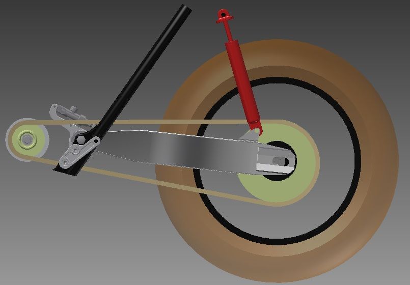
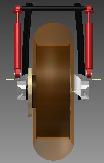
This is a crude model of work done so far with the components I have sourced for the bike: XJR1300 swingarm, R1 5VY rear wheel.
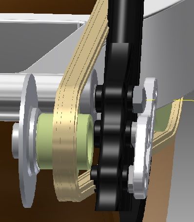
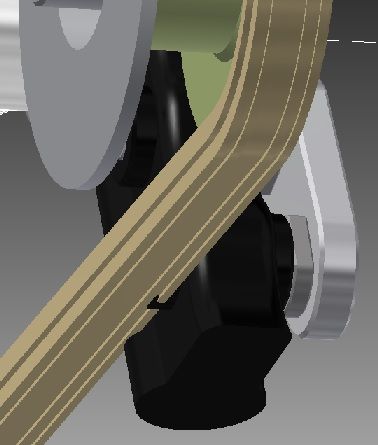
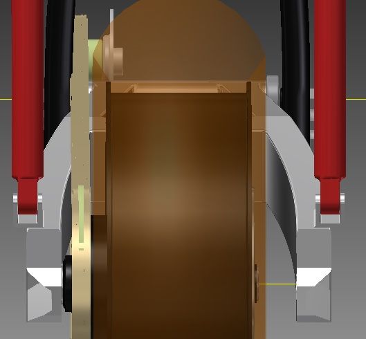
I have modelled a 520 x-ring chain running on a 19T 520 offset sprocket and a 45T 520 rear sprocket. Not sure these are the sizes I will go with yet and may even go to a 530 chain as the 530 chain is only marginally wider overall (length of rivet pins). What I do know is that with this combination and no machining of the sprocket carrier the chain will cut through the frame rails and the lower foot-rest mount boss on the inside of the frame:
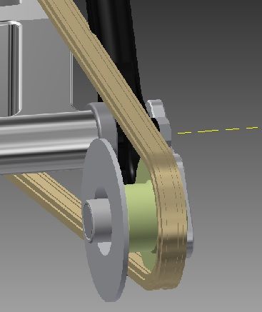
The model is fairly accurate (to within 1mm) of reality and calls for a 25mm (1 inch) offset front sprocket, which I have verified with actual measurements I have made with a straight-line mounted off the sprocket carrier running forward to the standard 630 sprocket.
According to the model I only have about 3mm to play with between the inside of the chain and the outermost side of the rear tyre. Of course this is a 200 section slick and I want to fit in a 200 section road tyre, so to be sure, next step is to get a 200 section road tyre fitted as I think this will be a slightly narrower tyre. Then I will need to accurately model the road tyre and see how much I have to play with before I make the decision what size chain I will use. If it all goes tits up I will have to go for a 190 section tyre, but I am pretty determined to get as fat a tyre in there as I can on the 6 inch rim.
We design and make many 1 off sprockets at work, so I intend to do this and also design an outrigger bearing and support plate (drag bike stylee but better) which will also incorporate a clutch cylinder from a modern Jap bike.
So to have Zed 1015 also confirm my virtual findings in the real world with his experience is reassuring and shows he knows his onions, so Cheers for that

I think that no matter what I do, I will be attacking the frame with the cut off disc in this area, which Is no surprise really. Making a neat job of the subsequent infill I will need to do, plus any additional bracing and strengthening will have to be done with great care.
More to come......


 [img]
[img]


![[img]http://i28.photobucket.com/albums/c207/mikeandbron2012/IMG_0152_zps1fbfeb7e.jpg[/img]](http://s28.photobucket.com/user/mikeandbron2012/media/IMG_0152_zps1fbfeb7e.jpg.html)
![[img]http://i28.photobucket.com/albums/c207/mikeandbron2012/IMG_0150_zps4489aabb.jpg[/img]](http://s28.photobucket.com/user/mikeandbron2012/media/IMG_0150_zps4489aabb.jpg.html)
![[img]http://i28.photobucket.com/albums/c207/mikeandbron2012/IMG_0151_zps94a73130.jpg[/img]](http://s28.photobucket.com/user/mikeandbron2012/media/IMG_0151_zps94a73130.jpg.html)
![[img]http://i28.photobucket.com/albums/c207/mikeandbron2012/IMG_0111_zps7e47a206.jpg[/img]](http://s28.photobucket.com/user/mikeandbron2012/media/IMG_0111_zps7e47a206.jpg.html)
![[img]http://i28.photobucket.com/albums/c207/mikeandbron2012/IMG_0107_zpsb0f91768.jpg[/img]](http://s28.photobucket.com/user/mikeandbron2012/media/IMG_0107_zpsb0f91768.jpg.html)
![[img]http://i28.photobucket.com/albums/c207/mikeandbron2012/IMG_0110_zps8044152a.jpg[/img]](http://s28.photobucket.com/user/mikeandbron2012/media/IMG_0110_zps8044152a.jpg.html)
![[img]http://i28.photobucket.com/albums/c207/mikeandbron2012/IMG_0105_zps37fd098f.jpg[/img]](http://s28.photobucket.com/user/mikeandbron2012/media/IMG_0105_zps37fd098f.jpg.html)
![[img]http://i28.photobucket.com/albums/c207/mikeandbron2012/IMG_0106_zpsa66166d4.jpg[/img]](http://s28.photobucket.com/user/mikeandbron2012/media/IMG_0106_zpsa66166d4.jpg.html)
![[img]http://i28.photobucket.com/albums/c207/mikeandbron2012/IMG_0113_zpsa09dc62e.jpg[/img]](http://s28.photobucket.com/user/mikeandbron2012/media/IMG_0113_zpsa09dc62e.jpg.html)
![[img]http://i28.photobucket.com/albums/c207/mikeandbron2012/IMG_0146_zps0cd97b71.jpg[/img]](http://s28.photobucket.com/user/mikeandbron2012/media/IMG_0146_zps0cd97b71.jpg.html)
![[img]http://i28.photobucket.com/albums/c207/mikeandbron2012/IMG_0147_zps992e52e4.jpg[/img]](http://s28.photobucket.com/user/mikeandbron2012/media/IMG_0147_zps992e52e4.jpg.html)
![[img]http://i28.photobucket.com/albums/c207/mikeandbron2012/IMG_0114_zps1f96fa23.jpg[/img]](http://s28.photobucket.com/user/mikeandbron2012/media/IMG_0114_zps1f96fa23.jpg.html)
![[img]http://i28.photobucket.com/albums/c207/mikeandbron2012/IMG_0148_zpsfd40c68c.jpg[/img]](http://s28.photobucket.com/user/mikeandbron2012/media/IMG_0148_zpsfd40c68c.jpg.html)
![[img]http://i28.photobucket.com/albums/c207/mikeandbron2012/IMG_0115_zps0ceb7bf7.jpg[/img]](http://s28.photobucket.com/user/mikeandbron2012/media/IMG_0115_zps0ceb7bf7.jpg.html)
![[img]http://i28.photobucket.com/albums/c207/mikeandbron2012/IMG_0154_zpsd155dc25.jpg[/img]](http://s28.photobucket.com/user/mikeandbron2012/media/IMG_0154_zpsd155dc25.jpg.html)